I have built at least 5 Repeaters using the Motorola Mitrek as a base. I Usually place them in a consolette or super consolette base station. This gives me a built in 12v supply (about 15-20 amps), a desktop cabinet,and a place to hide the controller. The basic conversion has beenextracted from the original conversion process that can be found at:
http://www.seits.org/repeater/mitrek/mitrek3.htm
However, this copy of the article has been edited to match my generalconversions.
Receiver Antenna connection
Now we need to install a second antenna connection for the receiver. Follow the connection from the Transmit/Receiver antenna relay (front casing)to the receiver, unsolder the mini coax and replace with a3.5 Foot longpiece of double shielded coax terminated with a female N connector anda hood. This will mount in the back chassis of the consolette onthe side near the power supply in the nicely provided knockout. MAKESURE THAT THE CONNECTOR IS INSTALLED BEFORE ANCHORING INTO THE CHASSIS. This will cause the connector to come from within the chassis. Thismakes the radio replaceable without a soldering iron and cutters!
Duplexing The Radio
Two very simple steps.
1) Clip one side of CR1 This will allowpower to stay on to the receiver crystals during transmit.
2) Clip one side of CR403. This will allowthe local speaker amplifier to remain in operation during transmission.
COS Signal
There are so many different mods for this, however, here is what I havedone. On the receiver, there is a test point marked 'E'. Mostradios have a terminal here, some do not. Connect a 4.7 to 10 K resistorfrom here to the union of the pads at JU3-A and JU3-B on the front interfacecard. This is on the solder side of the board toward the center of theradio. This signal will now appear on pin 18 of the main connector.
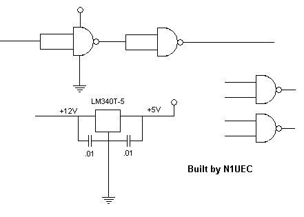
Take that signal and pass it though a 'double gated inverter' (see schematicbelow). I use two gates of a 4011. This is a very common chipand is very resilient. Being a quad NAND gate, additional signals,(PL, etc.) can also be gated into the COS line. I also use a 7805regulator to supply Vdd to the 4011 so i have a solid reference voltage. This gets used on the NHRC-2 COS+.
MAIN CONNECTOR PIN OUTS
Here are the pin outsfor the main connector
1. Xmit Audio (since this is the Mic line, it will get Pre emphasized)
2. Gnd
3. Speaker +
4. + 12V
5. Speaker -
6. Gnd
7. Gnd
8. F1 Select (Gnd)
11. Detectoraudio (No De emphasis)
12. + 12V
13. PTT
14. Squelch(Return from squelch pot)
15. Volume(Return from volume pot)
17 Gnd
18. COSTrigger (See Above)
19 + 12V
Squelch and Volume Control
The detector feeds not only the controller for receive audio but alsoboth the squelch and volume controls. Since we have done away with theoriginal controls, we have to recreate these controls. This takes two potsof 25K ohms each, a 3.3K resistor, and a 10K resistor.
Connect the 3.3K resistor to the detector line, pin 11, and one sideof one of the pots. Ground the other side of the pot and connect the wiperto pin 14, the squelch return line.
Proceed the same way with the other pot, substituting the 10K for the3.3K and connecting the wiper to the volume return, pin 15.
One note here: do NOT ground either speaker lead when hooking up thelocal speaker, as this could seriously damage the audio output of the radio.
Pre & De emphasis
A word about emphasis.
The mitrek (as well as most other radios) will not provide a de emphasizedaudio path if that audio is taken from the detector stage. This isboth a good and bad thing. Good because you can find any and allsignals here, bad because without some level of de emphasis you cannotfeed the audio directly to the transmit line UNLESS you send it in to the'pl' input. since the 'pl' input is not available on the front connector,your controller must do the de emphasis. If the de emphasis is notavailable on the controller, you may add the circuit I have used twiceseen here to create a buffered de emphasized audio path,
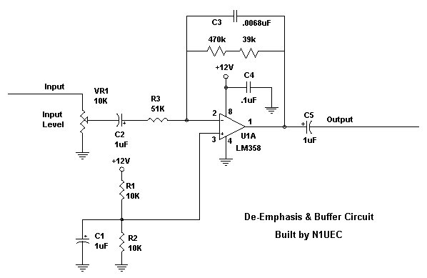
Looking at the schematic your going to say, 'why did you use a 470k& a 39k in series when you should have used a 510k?', well, in onecase i did, in another, i had run out and used what you see here. for simplicity, (as I was documenting the later), this is what youget!). If you do not like the audio quality, play with differentop-amps.