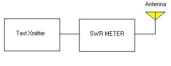
Antenna SWR tests:
Notes: Be sure the cable from the test transmitter to the swr meter is ½ wavelength long:
Be sure you DO NOT ADD any cable from the swr meter to the antenna feed cable.
Perform test with test transmitter on transmit and receive frequencies.
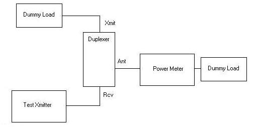
Duplexer SWR Tests:

Set-up as above, antenna dummy load should be placed on or as close as possible to the duplexer.
Cable from test transmitter to swr meter should be ½ wavelength.
Perform above test, then switch swr meter and test transmitter
to receiver port, retest, and then switch to antenna port and retest.
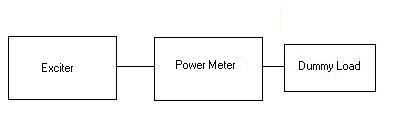
Notes: Use ½ wavelength jumper between meter and exciter.
Use the same method for testing the power amplifier. Cable
from the exciter to the power amplifier should be ½ wavelength or
a multiple if possible.
Perform the above power test for the receive frequency (using the test transmitter).
Use a Frequency Counter to check the transmit frequency.
Use a deviation meter to check input vs. output deviation.
Measurements should be taken at 1.5, 2.5,3.5,4.5,5.5, and 6.5 kHz of input
deviation. Output should match input below 5kHz, at 5.5kHz and above no
more than 5khz of deviation should be visible.
Receiver Measurements:
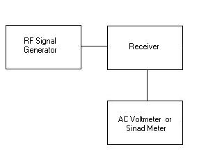
AC Voltmeter and/or sinad meter should be connected across the receiver speaker and the output of the receiver (volume control) must not be adjusted during tests. Set the volume for a 75-80% full scale reading un-squelched (with noise). An analog voltmeter or an oscilloscope is preferred for these measurements.
If the input signal level is not calibrated, try to note the values as relative. If different test setups will be used, try to get both setups together at one time so readings on one may be referenced to readings on the other.
Cable from the signal generator to the receiver should be ½ wavelength.
Quieting can be estimated without a sinad meter using the following technique:
De-sense testing:
How do I know if there is de-sense ?
With a weak signal on the input (read as scratchy), turn off the transmitter with the local transmitter disable switch. If the signal sounds better (on the local receiver) without the transmitter running, you have de-sense.
How can I measure how bad the desense is ?
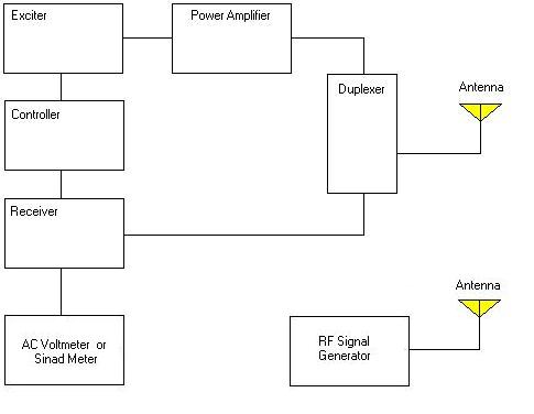
As seen in the earlier tests, the ac voltmeter or sinad meter will be connected to the local speaker terminals. In this case the RF signal generator will be connected to an antenna to leak the signal into the system. These measurements are only RELATIVE. Very sophisticated connections are required to make duplicateable measurements. For this reason, it is a good idea to start with a receiver only measurement for full quieting and for ½ noise as seen above but using this configuration as well and then adding in the transmitter and/or the power amplifier recording the information all along the way. This will allow us to compare the measurements from two different sessions. Dont forget to also do the receiver sensitivity measurements for sinad or the numbers cannot be cross-referenced.
IMPORTANT SAFETY NOTES:
Do not allow the signal generator antenna and the repeater
antenna to be physically close to one another or significant damage to
the signal generator may result.
General Repeater Notes:
Try to always use double shielded cable for all RF connections on the repeater.
All interconnecting RF cables should be in multiples of ½ wavelength at the operating frequency. This will allow proper impedance matching at both ends of the cable.
All miscellaneous leads for all connections of any signals that feed from one component to another should be shielded.
All RF entities, (the receiver, transmitter, power amplifier) etc. should be in rf tight enclosures that utilize feed through isolation caps for interconnections.
All control entities should be shielded from rf wherever possible.
NO ADJUSTMENTS TO DUPLEXER CAVITIES SHOULD EVER BE PERFORMED WITHOUT ADEQUATE TEST EQUIPMENT. REGARDLESS OF ANY MEASUREMENTS PERFORMED IN THE FIELD!!!!!!!!!!!!!!!
Remember, if all you do is look, (read as test and measure
but NOT adjust), nothing can/should be damaged.